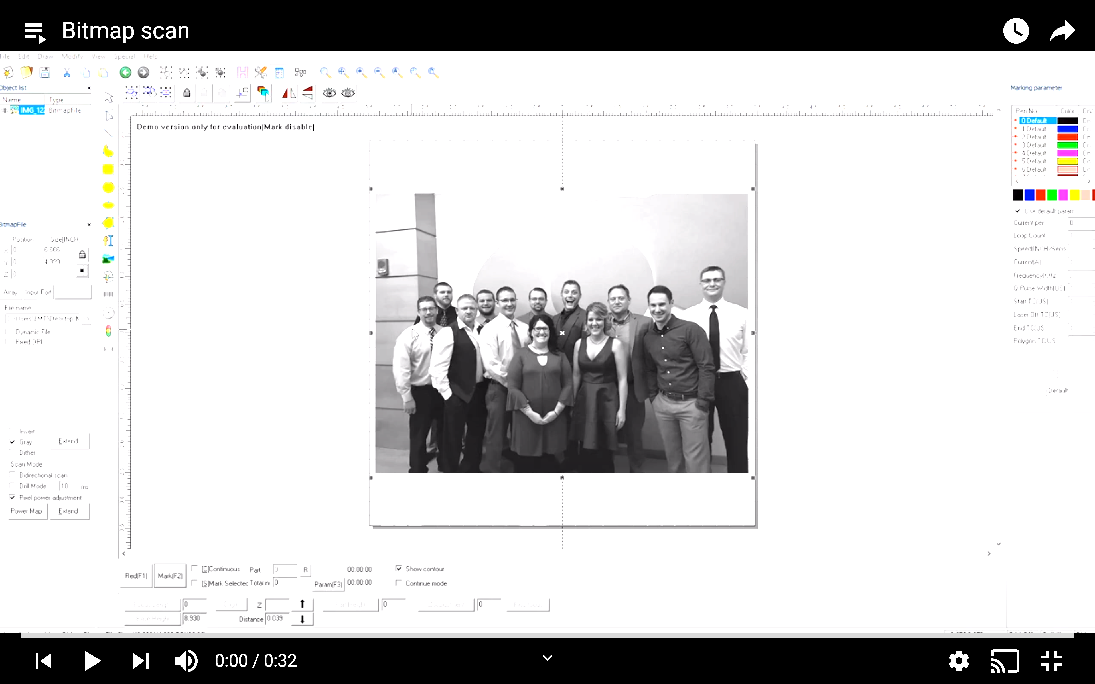
1. Insert the bitmap
2. View the power map to see the shades that will be marked.
3. If it is a black-and-white image, disable the white shades by going into the “extend” tab and setting the “Disable Mark Low Point” to around 5. This way the machine will not spend time marking the lighter shades.
4. If it is a colored image use the Gray button.
5. You can use the “Disable Mark Low Point” for these images as well.
6. The dither function allows a shaded image to act like a black-and-white image.
7. Invert can be used if marking black materials.
8. The minimum and maximum gray settings within the power map can be utilized to limit the power range to only the shades contained in the image.
9. The Power setting of the main software screen will determine the max power / “100%” within the bitmap, which can be adjusted along with the other marking settings such as speed and frequency to create the contrast marking.
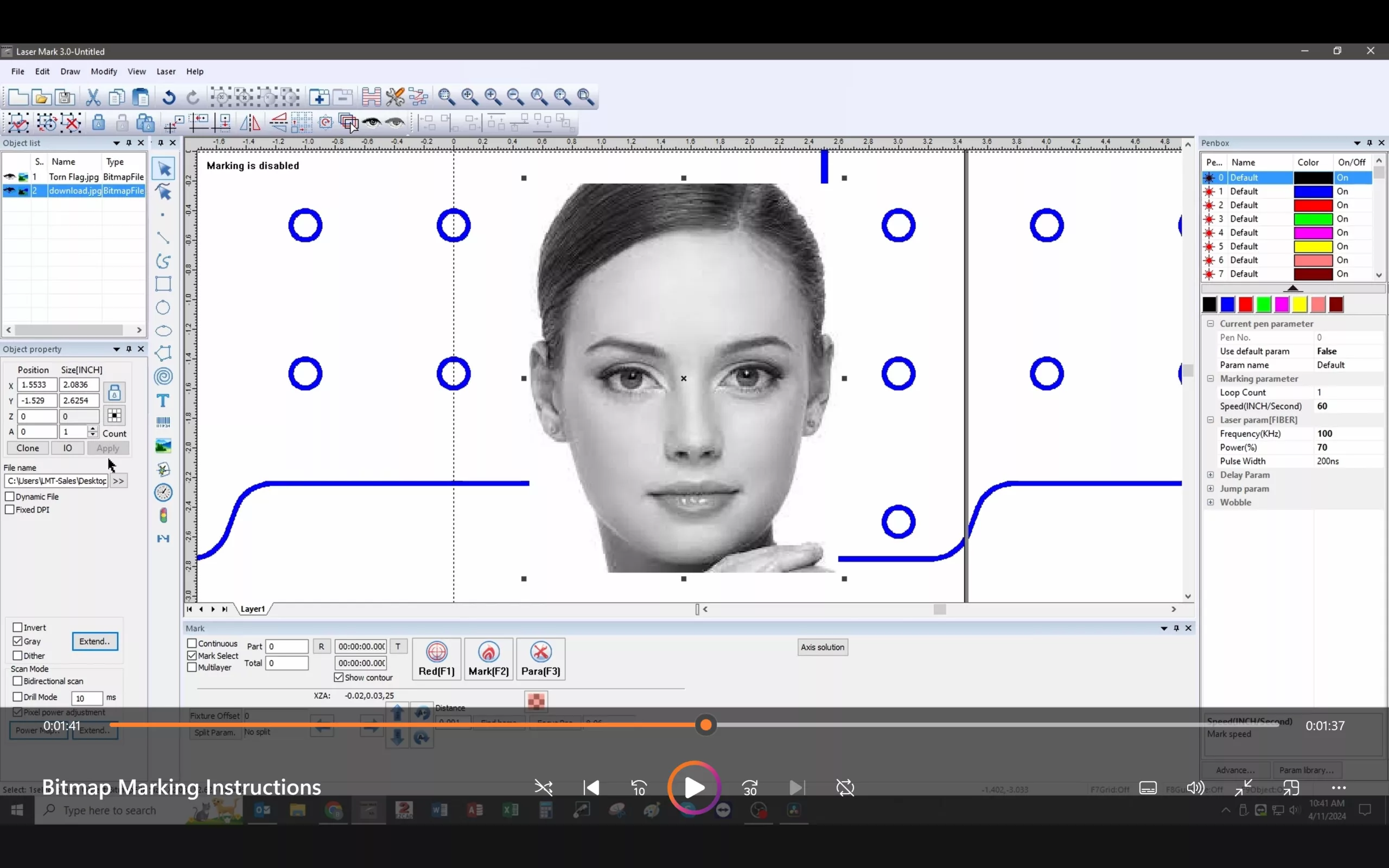
Bitmap Marking


 X-Axis Maintenance